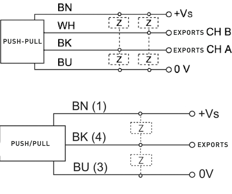
The forward and reverse dual-channel speed sensor has no contact with the measured gear, has no wear, and is easy to install. The output waveform is a square wave with a duty cycle of about 50%. The sensor has good low-frequency and high-frequency characteristics. The low frequency can be as high as 0Hz, which can be used for zero-speed measurement of rotating machinery. Since the sensor can give two speed signals with a certain phase difference, it can distinguish forward and reverse rotation; the high frequency can be as high as 20KHz, which can meet the needs of most industries. High speed measurement requirements in the field

| Product Paramenters |
| Working power supply | Ub=15VDC±30% (8V~28V) |
| Power consumption current | ≤35mA |
| Operating temperature | -40℃~125℃(head) |
| Vibration resistance | Vibration (10Hz~2KHz) 30g, shock 100g |
| Sealing | IP6813. |
| Power polarity protection | YES |
| Output short circuit protection | YES |
| Dielectric strength | 1000V 50Hz, 1min (channel and shell) |
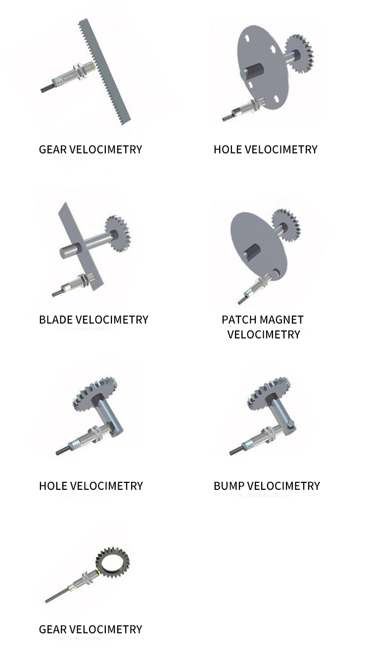
Install according to the application example in the fourth section of this manual. When the rotation direction is defined as forward rotation as shown in Figure 4, the output waveform is channel 1 leading channel 2 by 90 degrees. The waveform diagram is as follows:

When the rotation direction is opposite to the direction shown in Figure 4, the channel 2 waveform will lead the channel 1 waveform by 90 degrees. The waveform diagram is as follows:

As can be seen from the above figure, forward and reverse can be distinguished by phase identification of the waveforms of channels 1 and 2.


